文章目录
- 1、现实差
- 2、 提高仿真度
-
- 前提
- 2.1、执行器模型
- 2.2、 延迟
- 3、 建立鲁棒控制器
-
- 3.1、随机动态参数
- 3.2、随机扰动
- 3.3、状态空间
1、现实差
因为并不存在能够完美捕捉现实的模拟器(环境),模拟与现实之间存在「现实差距」(Reality Gap),模型的输入分布在策略训练(模拟)和策略执行(现实)之间存在动态变化和差异性。如果继续在这种有缺陷的模拟环境中训练策略产生控制行为,这种行为无法应对现实环境中的任何微小变化。此外,对于一些机器人动作模拟问题(如滑动摩擦力和接触力),其背后的物理现象仍然没有在模拟器上百分百模拟,这就意味着根本不可能在模拟环境中对一些现实中的机器人动作进行完全精确的模拟。由于这种现实差距,在仿真中学习的机器人控制器在现实环境中往往表现不佳。minitaur研究人员就提出两种方法来缩小差距:提高仿真逼真度和学习鲁棒控制器。
2、 提高仿真度
前提
首先为minitaur机器人创建一个精确的urdf文件用于仿真,假设每个部件的密度是均匀的,根据每个连杆的形状和质量来估计它的惯量。
2.1、执行器模型
用位置控制来驱动电机,添加约束en+1=0,即当前时间的误差为零,公式为:
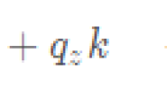
 其中,
其中,
 尽管这看起来和PD伺服控制看起来很像,但有一点关键的区别是该式保证电动机的角度和速度在当前时间步满足约束,而PD伺服控制使用当前电机角和速度来决定如何驱动电机。因此,如果使用大的增益,电机可以保持稳定的模拟,但在现实中振荡。 为了消除执行器的模型误差,我们根据理想直流电机的动力学特性建立了执行器模型。参数R RR 、K t K_tKt在电机的说明书里面应该有提及。给定PWM信号,电机的转矩为:
 I是电枢电流,
 利用上面的模型,我们观察到真实的Minitaur经常会下沉或无法抬起,而同样的控制器在仿真中工作良好。这是因为线性扭矩-电流关系只适用于理想的电机。实际上,随着电流的增加,转矩就会饱和。为此,我们构造了一个分段线性函数来描述这种非线性的转矩-电流关系。在仿真中,一旦电流由PWM(式(5)和(6)计算出来,我们使用这个分段函数来查找相应的转矩。 在位置控制中,PWM由PD伺服控制。
![]() 其中V 为供电电压,另外,我们参考Ghost Robotics在微控制器上的PD实现,将目标速度设置为
其中V 为供电电压,另外,我们参考Ghost Robotics在微控制器上的PD实现,将目标速度设置为
![]() 。实验得到的曲线如下,可以看出仿真轨迹与现实轨迹几乎一致:
。实验得到的曲线如下,可以看出仿真轨迹与现实轨迹几乎一致:
 pybullet中的实现 要是用上述执行器模型,需要在环境中设置self._accurate_motor_model_enabled 和self._pd_control_enabled 同时为True。默认仿真环境中这两项同时为False,即执行器直接将角度控制信号丢给电机模型进行角度控制
minitaur仿真环境里面还有一个motor仿真,结合motor来看就能完整地实现了上述的控制模型
  def ApplyAction(self, motor_commands, motor_kps=None, motor_kds=None):
    """Set the desired motor angles to the motors of the minitaur.

    The desired motor angles are clipped based on the maximum allowed velocity.
    If the pd_control_enabled is True, a torque is calculated according to
    the difference between current and desired joint angle, as well as the joint
    velocity. This torque is exerted to the motor. For more information about
    PD control, please refer to: https://en.wikipedia.org/wiki/PID_controller.

    Args:
      motor_commands: The eight desired motor angles.
      motor_kps: Proportional gains for the motor model. If not provided, it
        uses the default kp of the minitaur for all the motors.
      motor_kds: Derivative gains for the motor model. If not provided, it
        uses the default kd of the minitaur for all the motors.
    """
    if self._motor_velocity_limit < np.inf:
      current_motor_angle = self.GetTrueMotorAngles()
      motor_commands_max = (current_motor_angle + self.time_step * self._motor_velocity_limit)
      motor_commands_min = (current_motor_angle - self.time_step * self._motor_velocity_limit)
      motor_commands = np.clip(motor_commands, motor_commands_min, motor_commands_max)
    # Set the kp and kd for all the motors if not provided as an argument.
    if motor_kps is None:
      motor_kps = np.full(8, self._kp)
    if motor_kds is None:
      motor_kds = np.full(8, self._kd)

    if self._accurate_motor_model_enabled or self._pd_control_enabled:
      q, qdot = self._GetPDObservation() # 返回角度值和速度(包含延时)
      qdot_true = self.GetTrueMotorVelocities()
      if self._accurate_motor_model_enabled:
        actual_torque, observed_torque = self._motor_model.convert_to_torque(
            motor_commands, q, qdot, qdot_true, motor_kps, motor_kds)
        if self._motor_overheat_protection:
          for i in range(self.num_motors):
            if abs(actual_torque[i]) > OVERHEAT_SHUTDOWN_TORQUE:
              self._overheat_counter[i] += 1
            else:
              self._overheat_counter[i] = 0
            if (self._overheat_counter[i] > OVERHEAT_SHUTDOWN_TIME / self.time_step):
              self._motor_enabled_list[i] = False

        # The torque is already in the observation space because we use
        # GetMotorAngles and GetMotorVelocities.
        self._observed_motor_torques = observed_torque

        # Transform into the motor space when applying the torque.
        self._applied_motor_torque = np.multiply(actual_torque, self._motor_direction)

        for motor_id, motor_torque, motor_enabled in zip(self._motor_id_list,
                                                         self._applied_motor_torque,
                                                         self._motor_enabled_list):
          if motor_enabled:
            self._SetMotorTorqueById(motor_id, motor_torque)
          else:
            self._SetMotorTorqueById(motor_id, 0)
      else:
        torque_commands = -1 * motor_kps * (q - motor_commands) - motor_kds * qdot

        # The torque is already in the observation space because we use
        # GetMotorAngles and GetMotorVelocities.
        self._observed_motor_torques = torque_commands

        # Transform into the motor space when applying the torque.
        self._applied_motor_torques = np.multiply(self._observed_motor_torques,
                                                  self._motor_direction)

        for motor_id, motor_torque in zip(self._motor_id_list, self._applied_motor_torques):
          self._SetMotorTorqueById(motor_id, motor_torque)
    else:
      motor_commands_with_direction = np.multiply(motor_commands, self._motor_direction)
      for motor_id, motor_command_with_direction in zip(self._motor_id_list,
                                                        motor_commands_with_direction):
        self._SetDesiredMotorAngleById(motor_id, motor_command_with_direction)
这里给出motor部分的代码:
"""This file implements an accurate motor model."""

import numpy as np
VOLTAGE_CLIPPING = 50
# TODO(b/73728631): Clamp the pwm signal instead of the OBSERVED_TORQUE_LIMIT.
OBSERVED_TORQUE_LIMIT = 5.7
MOTOR_VOLTAGE = 16.0
MOTOR_RESISTANCE = 0.186
MOTOR_TORQUE_CONSTANT = 0.0954
MOTOR_VISCOUS_DAMPING = 0
MOTOR_SPEED_LIMIT = MOTOR_VOLTAGE / (MOTOR_VISCOUS_DAMPING + MOTOR_TORQUE_CONSTANT)
NUM_MOTORS = 8


class MotorModel(object):
  """The accurate motor model, which is based on the physics of DC motors.

  The motor model support two types of control: position control and torque
  control. In position control mode, a desired motor angle is specified, and a
  torque is computed based on the internal motor model. When the torque control
  is specified, a pwm signal in the range of [-1.0, 1.0] is converted to the
  torque.

  The internal motor model takes the following factors into consideration:
  pd gains, viscous friction, back-EMF voltage and current-torque profile.
  """

  def __init__(self, torque_control_enabled=False, kp=1.2, kd=0):
    self._torque_control_enabled = torque_control_enabled
    self._kp = kp
    self._kd = kd
    self._resistance = MOTOR_RESISTANCE
    self._voltage = MOTOR_VOLTAGE
    self._torque_constant = MOTOR_TORQUE_CONSTANT
    self._viscous_damping = MOTOR_VISCOUS_DAMPING
    self._current_table = [0, 10, 20, 30, 40, 50, 60]
    self._torque_table = [0, 1, 1.9, 2.45, 3.0, 3.25, 3.5]
    self._strength_ratios = [1.0] * NUM_MOTORS
	.
	.
	.
  def convert_to_torque(self,
                        motor_commands,
                        motor_angle,
                        motor_velocity,
                        true_motor_velocity,
                        kp=None,
                        kd=None):
    """Convert the commands (position control or torque control) to torque.

    Args:
      motor_commands: The desired motor angle if the motor is in position
        control mode. The pwm signal if the motor is in torque control mode.
      motor_angle: The motor angle observed at the current time step. It is
        actually the true motor angle observed a few milliseconds ago (pd
        latency).
      motor_velocity: The motor velocity observed at the current time step, it
        is actually the true motor velocity a few milliseconds ago (pd latency).
      true_motor_velocity: The true motor velocity. The true velocity is used
        to compute back EMF voltage and viscous damping.
      kp: Proportional gains for the motors' PD controllers. If not provided, it
        uses the default kp of the minitaur for all the motors.
      kd: Derivative gains for the motors' PD controllers. If not provided, it
        uses the default kp of the minitaur for all the motors.

    Returns:
      actual_torque: The torque that needs to be applied to the motor.
      observed_torque: The torque observed by the sensor.
    """
    if self._torque_control_enabled:
      pwm = motor_commands
    else:
      if kp is None:
        kp = np.full(NUM_MOTORS, self._kp)
      if kd is None:
        kd = np.full(NUM_MOTORS, self._kd)
      pwm = -1 * kp * (motor_angle - motor_commands) - kd * motor_velocity

    pwm = np.clip(pwm, -1.0, 1.0)
    return self._convert_to_torque_from_pwm(pwm, true_motor_velocity)

  def _convert_to_torque_from_pwm(self, pwm, true_motor_velocity):
    """Convert the pwm signal to torque.

    Args:
      pwm: The pulse width modulation.
      true_motor_velocity: The true motor velocity at the current moment. It is
        used to compute the back EMF voltage and the viscous damping.
    Returns:
      actual_torque: The torque that needs to be applied to the motor.
      observed_torque: The torque observed by the sensor.
    """
    observed_torque = np.clip(
        self._torque_constant * (np.asarray(pwm) * self._voltage / self._resistance),
        -OBSERVED_TORQUE_LIMIT, OBSERVED_TORQUE_LIMIT)

    # Net voltage is clipped at 50V by diodes on the motor controller.
    voltage_net = np.clip(
        np.asarray(pwm) * self._voltage -
        (self._torque_constant + self._viscous_damping) * np.asarray(true_motor_velocity),
        -VOLTAGE_CLIPPING, VOLTAGE_CLIPPING)
    current = voltage_net / self._resistance
    current_sign = np.sign(current)
    current_magnitude = np.absolute(current)
    # Saturate torque based on empirical current relation.
    actual_torque = np.interp(current_magnitude, self._current_table, self._torque_table)
    actual_torque = np.multiply(current_sign, actual_torque)
    actual_torque = np.multiply(self._strength_ratios, actual_torque)
    return actual_torque, observed_torque
2.2、 延迟
延迟是反馈控制不稳定的主要原因之一。从发送电机命令导致机器人状态改变到传感器测量此变化并反馈给控制器之间的时间延迟。在Bullet中,电机命令立即生效,传感器立即报告状态。这种瞬时反馈使得反馈控制器在仿真中的稳定性比硬件上的实现要大得多。因此,我们经常看到在模拟中学习的反馈策略开始振荡、发散,最终在现实世界中失败。 为了应对延迟,我们创建一个历史记录表,用于记录状态值及其测量时间 鲁棒控制的目的是在存在模型误差的情况下实现鲁棒性能。因此,即使模拟的动态与真实世界的动态并不相同,也更容易将鲁棒控制器转移到真实世界。在本文中,我们尝试了三种不同的方法来学习鲁棒控制器随机动态参数,添加随机扰动和使用一个紧凑的状态空间。 之前的研究表明,在训练过程中随机化动态参数可以提高学习控制器的鲁棒性[39,44]。在每一轮训练开始时,我们随机抽取一组物理参数并在模拟中使用它们。在一定范围内均匀抽取样品。
![]() ,其中
,其中
![]() ,在当前步n,当控制器需要一个状态时,我们会在历史记录中搜索两个邻近的状态值O i 和O i + 1,其中
,在当前步n,当控制器需要一个状态时,我们会在历史记录中搜索两个邻近的状态值O i 和O i + 1,其中
![]() ,然后对他们进行线性插值。
,然后对他们进行线性插值。def _GetDelayedObservation(self, latency):
"""Get observation that is delayed by the amount specified in latency.
Args:
latency: The latency (in seconds) of the delayed observation.
Returns:
observation: The observation which was actually latency seconds ago.
"""
if latency <= 0 or len(self._observation_history) == 1:
observation = self._observation_history[0]
else:
n_steps_ago = int(latency / self.time_step)
if n_steps_ago + 1 >= len(self._observation_history):
return self._observation_history[-1]
remaining_latency = latency - n_steps_ago * self.time_step
blend_alpha = remaining_latency / self.time_step
observation = ((1.0 - blend_alpha) * np.array(self._observation_history[n_steps_ago]) +
blend_alpha * np.array(self._observation_history[n_steps_ago + 1]))
return observation
3、 建立鲁棒控制器
3.1、随机动态参数
 由于动态随机化对健壮性[55]的最优性进行了交换,所以我们仔细选择表中的参数及其范围,以避免学习过于保守的跑步步态。质量和电机摩擦是常用的随机参数[44,39]。由于我们在系统辨识时测量过它们,所以我们给出了它们的保守范围,但我们对惯性的确定程度较低,因为惯性是基于均匀密度假设估计的。还有一些量随时间变化。例如,电机的强度会因磨损而变化。由于非实时系统的存在,控制步骤和延迟可能会出现波动。电池电压可以根据是否充满电而变化。基于上述原因,我们选择根据实际测量值和较小的安全裕度随机化这些参数及其范围。准确识别接触参数是一个挑战。虽然Bullet物理库使用基于lcp的接触模型并提供了许多可调参数,但我们选择将重点放在横向摩擦上,而将其他参数保留为默认值。我们随机选取了摩擦系数在0.5和1.25之间的样本,因为这是Minitaur的橡胶脚和各种地毯[56]之间的摩擦系数的典型范围。由于实际的IMU测量往往带有偏置和噪声,我们还在模拟的IMU读数中加入了少量的高斯噪声。 pybullet中de实现:
干扰模块
SENSOR_NOISE_STDDEV = (0.0, 0.0, 0.0, 0.0, 0.0)
def _AddSensorNoise(self, sensor_values, noise_stdev):
    if noise_stdev <= 0:
      return sensor_values
    observation = sensor_values + np.random.normal(scale=noise_stdev, size=sensor_values.shape)
    return observation
以电机角度为例,其余数值类似
仿真环境中的真实值
def GetTrueMotorAngles(self):
    """Gets the eight motor angles at the current moment, mapped to [-pi, pi].

    Returns:
      Motor angles, mapped to [-pi, pi].
    """
    # getJointState()函数返回关节角度,速度,关节受力(有力传感器的前提下),扭矩
    motor_angles = [
        self._pybullet_client.getJointState(self.quadruped, motor_id)[0]
        for motor_id in self._motor_id_list
    ]
    # self._motor_direction = [-1, -1, -1, -1, 1, 1, 1, 1] 根据电机安装时的方向进行设定
    motor_angles = np.multiply(motor_angles, self._motor_direction)
    return motor_angles
加入噪声的返回值
def GetMotorAngles(self):
    """Gets the eight motor angles.

    This function mimicks the noisy sensor reading and adds latency. The motor
    angles that are delayed, noise polluted, and mapped to [-pi, pi].

    Returns:
      Motor angles polluted by noise and latency, mapped to [-pi, pi].
    """
    motor_angles = self._AddSensorNoise(np.array(self._control_observation[0:self.num_motors]),
                                        self._observation_noise_stdev[0])
    return MapToMinusPiToPi(motor_angles)
def MapToMinusPiToPi(angles):
    """Maps a list of angles to [-pi, pi].

    Args:
      angles: A list of angles in rad.
    Returns:
      A list of angle mapped to [-pi, pi].
    """
    mapped_angles = copy.deepcopy(angles)
3.2、随机扰动
另一种提高学习控制器鲁棒性的方法是加入随机扰动。在训练过程中,每仿真200步(1.2s),在仿真的Minitaur主体上增加一个力。扰动持续十步(0.06s),方向随机,大小随机,范围为130N ~ 220N。扰动会使模拟的minitaur失去平衡,因此它需要学习如何在不同的情况下恢复平衡。
_PERTURBATION_START_STEP = 100
_PERTURBATION_INTERVAL_STEPS = 200
_PERTURBATION_DURATION_STEPS = 10
_HORIZONTAL_FORCE_UPPER_BOUND = 120
_HORIZONTAL_FORCE_LOWER_BOUND = 240
_VERTICAL_FORCE_UPPER_BOUND = 300
_VERTICAL_FORCE_LOWER_BOUND = 500
  def randomize_step(self, env):
    """Randomizes simulation steps.

    Will be called at every timestep. May add random forces/torques to Minitaur.

    Args:
      env: The Minitaur gym environment to be randomized.
    """
    base_link_ids = env.minitaur.chassis_link_ids
    if env.env_step_counter % self._perturbation_interval_steps == 0:
      self._applied_link_id = base_link_ids[np.random.randint(0, len(base_link_ids))]
      horizontal_force_magnitude = np.random.uniform(self._horizontal_force_bound[0],
                                                     self._horizontal_force_bound[1])
      theta = np.random.uniform(0, 2 * math.pi)
      vertical_force_magnitude = np.random.uniform(self._vertical_force_bound[0],
                                                   self._vertical_force_bound[1])
      self._applied_force = horizontal_force_magnitude * np.array(
          [math.cos(theta), math.sin(theta), 0]) + np.array([0, 0, -vertical_force_magnitude])

    if (env.env_step_counter % self._perturbation_interval_steps <
        self._perturbation_duration_steps) and (env.env_step_counter >=
                                                self._perturbation_start_step):
      env.pybullet_client.applyExternalForce(objectUniqueId=env.minitaur.quadruped,
                                             linkIndex=self._applied_link_id,
                                             forceObj=self._applied_force,
                                             posObj=[0.0, 0.0, 0.0],
                                             flags=env.pybullet_client.LINK_FRAME)
3.3、状态空间
我们发现,状态空间的设计也起到了缩小现实差距的重要作用。如果状态空间是高维的,则学习策略很容易与仿真环境过度拟合,难以转化为真实的机器人。在本文中,我们使用了一个紧凑的状态空间(在第一点提及过),从而减少了对不重要的模拟细节进行过度拟合的空间。


