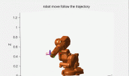
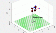
1、前记:
这几天同样在MATLAB官网上学习了些机器人相关的基础知识。看到官方新推出的机器人系统工具箱(Robotics System Toolbox)的功能在很多方面都强于Robotics Toolbox,而且要更好的利用其学习必须结合到ROS一起学习。之前一直犹豫是因为不熟悉ROS和Ubuntu系统,另外想装虚拟机又嫌麻烦,但从长远看十分有必要学习ROS了,想到自己基础薄弱便担心其路途遥远啊~ ~//
上下求索吧,以下是一个涉及逆运动学的二维轨迹跟踪例子。用机器人系统工具箱函数做的,参看网址在文末。
%% 2-D Path Tracing With Inverse Kinematics

%% Introduction

% This example shows how to calculate inverse kinematics for a simple 2D

% manipulator using the <docid:robotics_ref.bvdhj7x-1 InverseKinematics> class.

% The manipulator robot is a simple 2-degree-of-freedom planar

% manipulator with revolute joints which is created by assembling rigid bodies into

% a <docid:robotics_ref.bvan8uq-1 RigidBodyTree> object. A circular trajectory is

% created in a 2-D plane and given as points to the inverse kinematics solver. The solver

% calculates the required joint positions to achieve this trajectory.

% Finally, the robot is animated to show the robot configurations that

% achieve the circular trajectory.


%本示例演示如何使用机器人来计算简单2D 机械手的逆运动学。

机械手机器人是一个简单的2自由度平面机械手,

它是通过将刚体装配成robotics.RigidBodyTree 对象。

在2维平面上创建一个圆形轨迹, 并将其作为反向运动学求解器的指向。

规划求解计算所需的关节位置以实现此轨迹。

最后, 对机器人进行了动画演示, 显示了实现圆形轨迹的机器人配置。

%


%% Construct The Robot

% Create a |RigidBodyTree| object and rigid bodies with their

% associated joints. Specify the geometric properties of each rigid body

% and add it to the robot.

% Start with a blank rigid body tree model


%构造机器人

创建一个RigidBodyTree对象和刚性体与他们的关联关节。指定每个刚体的几何性质并将其添加到机器人中。

从一个空白的刚体树模型开始

robot = robotics.RigidBodyTree('DataFormat','column','MaxNumBodies',3);

%%

% Specify arm lengths for the robot arm.//指定机械手臂的长度

L1 = 0.4;

L2 = 0.3;

%%

% Add |'link1'| body with |'joint1'| joint.//添加'link1'身体与'joint1'关节。

body = robotics.RigidBody('link1');

joint = robotics.Joint('joint1', 'revolute');

setFixedTransform(joint,trvec2tform([0 0 0]));

joint.JointAxis = [0 0 1];

body.Joint = joint;

addBody(robot, body, 'base');

%%

% Add |'link2'| body with |'joint2'| joint.//添加'link2'身体与'joint2'关节。

body = robotics.RigidBody('link2');

joint = robotics.Joint('joint2','revolute');

setFixedTransform(joint, trvec2tform([L1,0,0]));

joint.JointAxis = [0 0 1];

body.Joint = joint;

addBody(robot, body, 'link1');

%%

% Add |'tool'| end effector with |'fix1'| fixed joint.//添加 " 'fix1'固定接头的'tool'端效应器。

body = robotics.RigidBody('tool');

joint = robotics.Joint('fix1','fixed');

setFixedTransform(joint, trvec2tform([L2, 0, 0]));

body.Joint = joint;

addBody(robot, body, 'link2');


%%

% Show details of the robot to validate the input properties. The robot

% should have two non-fixed joints for the rigid bodies and a fixed body

% for the end-effector.


%显示机器人的详细信息以验证输入属性。机器人应该有两个非固定的关节

为刚体和一个固定的机构为末端执行器。

%

showdetails(robot)


%% Define The Trajectory

% Define a circle to be traced over the course of 10 seconds. This circle

% is in the _xy_ plane with a radius of 0.15.


%定义轨迹:定义一个圆, 在10秒的过程中跟踪。这个圆圈在 xy 平面上, 半径为0.15。

%

t = (0:0.2:10)'; % Time

count = length(t);

center = [0.3 0.1 0];

radius = 0.15;

theta = t*(2*pi/t(end));

points = center + radius*[cos(theta) sin(theta) zeros(size(theta))];


%% Inverse Kinematics Solution

% Use an |InverseKinematics| object to find a solution of robotic

% configurations that achieve the given end-effector positions along the

% trajectory.


%逆运动学解:使用InverseKinematics对象找到机器人配置的解决方案, 以实现沿轨迹给定的最终末端位置。


%%

% Pre-allocate configuration solutions as a matrix |qs|.//预分配配置解决方案作为矩阵qs.

q0 = homeConfiguration(robot);

ndof = length(q0);

qs = zeros(count, ndof);

%%

% Create the inverse kinematics solver. Because the _xy_ Cartesian points are the

% only important factors of the end-effector pose for this workflow,

% specify a non-zero weight for the fourth and fifth elements of the

% |weight| vector. All other elements are set to zero.


%创建反向运动学求解器。因为 xy 笛卡尔点是此工作流的末端姿态的唯一重要因素,

 所以请为weight向量的第四和第五元素指定一个非零权重。所有其他元素都设置为零。

%


ik = robotics.InverseKinematics('RigidBodyTree', robot);

weights = [0, 0, 0, 1, 1, 0];

endEffector = 'tool';


%%

% Loop through the trajectory of points to trace the circle. Call the |ik|

% object for each point to generate the joint configuration that achieves

% the end-effector position. Store the configurations to use later.


%通过点的轨迹循环来跟踪圆。调用每个点的ik对象以生成实现末端位置的关节配置。存储要稍后使用的配置。

%


qInitial = q0; % Use home configuration as the initial guess

for i = 1:count

    % Solve for the configuration satisfying the desired end effector

    % position

    point = points(i,:);

    qSol = ik(endEffector,trvec2tform(point),weights,qInitial);

    % Store the configuration

    qs(i,:) = qSol;

    % Start from prior solution

    qInitial = qSol;

end


%% Animate The Solution

% Plot the robot for each frame of the solution using that specific robot

% configuration. Also, plot the desired trajectory.

%%

% Show the robot in the first configuration of the trajectory. Adjust the

% plot to show the 2-D plane that circle is drawn on. Plot the desired

% trajectory.


%对解决方案进行动画处理:使用特定的机器人配置为解决方案的每个帧绘制机器人。

同时, 绘制所需的轨迹。在轨迹的第一个配置中显示机器人。调整图形以显示2维平面,

该圆被绘制。绘制所需的轨迹。

%


figure

show(robot,qs(1,:)');

view(2)

ax = gca;

ax.Projection = 'orthographic';

hold on

plot(points(:,1),points(:,2),'k')

axis([-0.1 0.7 -0.3 0.5])


%%

% Set up a <docid:robotics_ref.mw_9b7bd9b2-cebc-4848-a38a-2eb93d51da03 Rate> object to display the robot

% trajectory at a fixed rate of 15 frames per second. Show the robot in

% each configuration from the inverse kinematic solver. Watch as the arm

% traces the circular trajectory shown.


%建立robotics.Rate对象以每秒15帧的固定速率显示机器人轨迹。

从逆运动学求解器中显示每个配置中的机器人。观察手臂跟踪显示的圆形轨迹。

%


framesPerSecond = 15;

r = robotics.Rate(framesPerSecond);

for i = 1:count

    show(robot,qs(i,:)','PreservePlot',false);

    drawnow

    waitfor(r);

end
2、删掉汉字,运行结果
3、从以上格式继续添加一个link.
代码:
%%机器人创建

robot = robotics.RigidBodyTree('DataFormat','column','MaxNumBodies',4);

L1 = 0.3;

L2 = 0.3;

L3=0.2;


body = robotics.RigidBody('link1');

joint = robotics.Joint('joint1', 'revolute');

setFixedTransform(joint,trvec2tform([0 0 0]));

joint.JointAxis = [0 0 1];

body.Joint = joint;

addBody(robot, body, 'base');


body = robotics.RigidBody('link2');

joint = robotics.Joint('joint2','revolute');

setFixedTransform(joint, trvec2tform([L1,0,0]));

joint.JointAxis = [0 0 1];

body.Joint = joint;

addBody(robot, body, 'link1');


body = robotics.RigidBody('link3');

joint = robotics.Joint('joint3','revolute');

setFixedTransform(joint, trvec2tform([L2,0,0]));

joint.JointAxis = [0 0 1];

body.Joint = joint;

addBody(robot, body, 'link2');


body = robotics.RigidBody('tool');

joint = robotics.Joint('fix1','fixed');

setFixedTransform(joint, trvec2tform([L3, 0, 0]));

body.Joint = joint;

addBody(robot, body, 'link3');

%%定义圆的轨迹

t = (0:0.2:10)'; % Time

count = length(t);

center = [0.5 0.1 0];

radius = 0.2;

theta = t*(2*pi/t(end));

points = center + radius*[cos(theta) sin(theta) zeros(size(theta))];

%%机器人初始配置

q0 = homeConfiguration(robot);

ndof = length(q0);

qs = zeros(count, ndof);

%%逆运动求解

ik = robotics.InverseKinematics('RigidBodyTree', robot);

weights = [0, 0, 0, 1, 1, 0];

endEffector = 'tool';


qInitial = q0; % Use home configuration as the initial guess

for i = 1:count

% Solve for the configuration satisfying the desired end effector

% position

point = points(i,:);

qSol = ik(endEffector,trvec2tform(point),weights,qInitial);

% Store the configuration

qs(i,:) = qSol;

% Start from prior solution

qInitial = qSol;

end

%%动画显示

figure

show(robot,qs(1,:)');

view(2)

ax = gca;

ax.Projection = 'orthographic';

hold on

plot(points(:,1),points(:,2),'k')

axis([-0.1 0.7 -0.3 0.5])


framesPerSecond = 15;

r = robotics.Rate(framesPerSecond);

for i = 1:count

show(robot,qs(i,:)','PreservePlot',false);

drawnow

waitfor(r);

end
结果:
参看网址:https://ww2.mathworks.cn/help/robotics/ug/2d-inverse-kinematics-example.html#d119e6514


